Eyetracking in a Task
Description
In the top left side panel of the task editor, click Edit next to the Physical Signals menu to open it and access the Eyetracking settings of the task.
![]()
To enable eyetracking in the task, please check the "Enable eye tracking in this task" checkbox. Before the study begins, participants will be prompted to select which webcam they would like to use, allowing for selection of a connected external webcam versus a built-in system. The main eyetracking calibration will automatically happen before the start of the first task with eyetracking enabled. Furthermore, if you enable eye tracking for this task, the head pose will be checked before each trial.
SVGs and Polygons for Using Complex Shapes as Masks and AOIs
As a part of the design process, you might want to consider utilizing SVG and Polygon shape objects in order to create complex shapes that can act as masks or AOIs. SVGs can be uploaded to Labvanced while Polygons can be drawn right within the app editor. These two options allow you to create complex shapes / areas and then use them as the basis of your eye-tracking experiment in Labvanced.
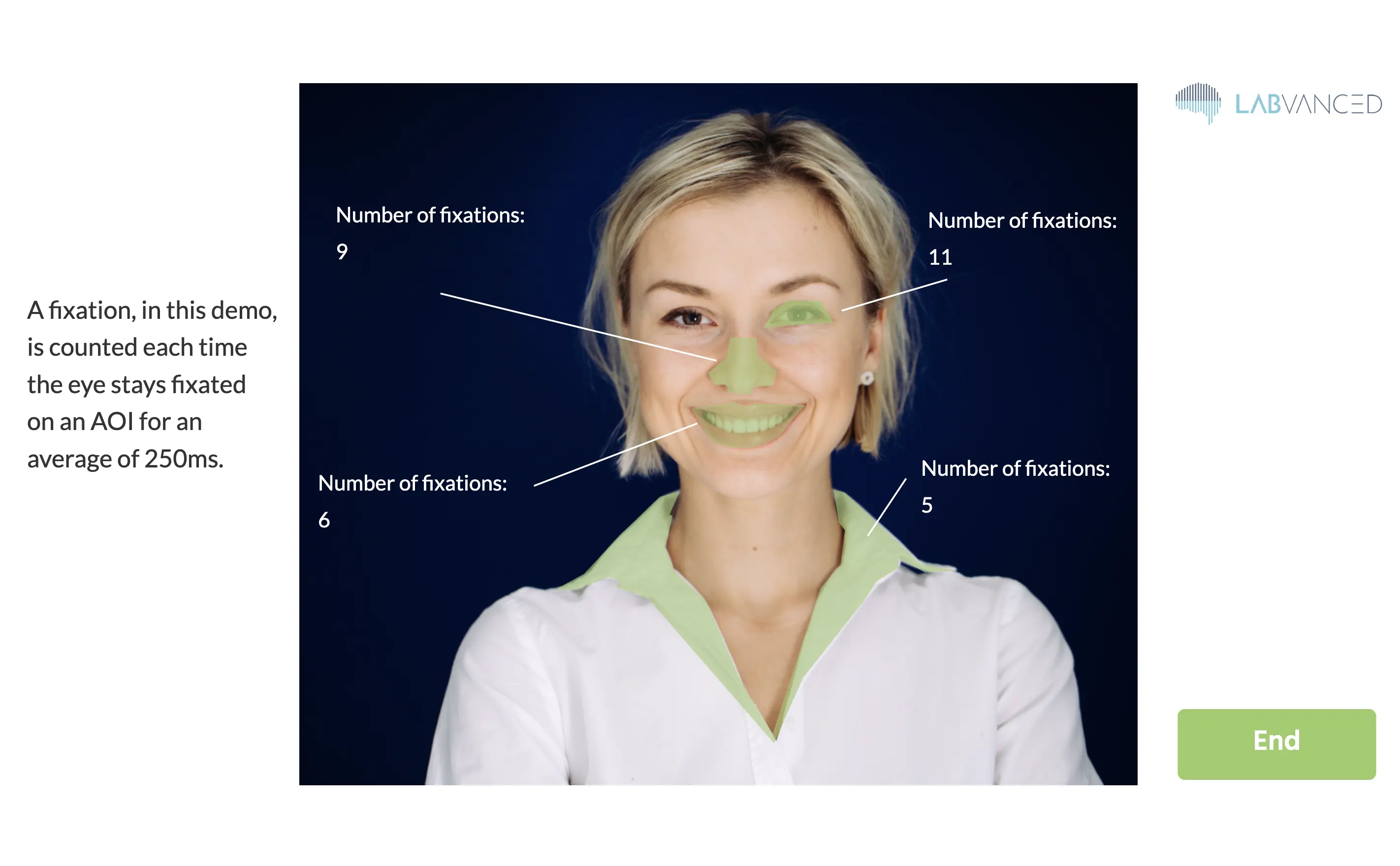
For example, you can implement a Polygon shape as a ‘trigger’ so that each time the participant fixates on it, the variable counting those fixations increases by one! You can see how this is set up in this demo here: https://www.labvanced.com/page/library/61117 by clicking ‘Inspect’ and opening the task to see the structure or ‘Participate’ to take part. The image below shows the outcome of the demo.

Please note that in the demo above, the fastest calibration settings are used (about 1-minute long) so that you can progress quickly through the experiment.
Between-Trial Fixations
In the Eyetracking Settings of the task, you can define the number of fixations to show between trials. These between-trial fixations have the following purpose:
- They are used to calculate the accuracy of the eyetracking before each trial.
- If you enable "per trial drift correction," the drift is calculated as the median difference between the shown fixation points and the predicted gaze locations. Every gaze prediction during the following trial will then be automatically corrected by this estimated offset.
Recording Eyetracking
The following is the recommended way to record a timeseries of [X,Y] coordinates of gaze locations.
- Create an Event with trigger "Eyetracking", which will automatically execute every time a new gaze location is predicted.
- To record the new gaze location, add the action "Set / Record Variable". In this action, on the left side, create a new recorded variable to store the gaze locations.
- In order to store a pair of x- and y-coordinates, it is best to choose format "Array".
- If you want to record all gaze locations over time, then switch the Record Type to "All changes / time series".
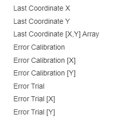
- On the right side of the action in the value select menu, select "Last Coordinate [X, Y] Array" from the "Eye Tracking" submenu (see figure).

The resulting recorded gaze coordinates will be in the design units that were used to position elements on your frames, such that you can easily associate coordinates to your stimulus locations.
Data Output
There are 4 basic values recorded per gaze data:
- X: x (horizontal) location in frame units
- Y: y (vertical) location in frame units
- T: precise/corrected timestamp for the gaze
- C:confidence of the gaze detection (0 indicate eye closure or no face /eye visible, 1 indicate 100% confidence)
Accuracy of Eyetracking
Please note that the accuracy of the predicted gaze coordinates varies over different subjects and their corresponding environment (i.e. lightning and camera). Therefore, we provide estimates of the prediction errors. These estimated errors can be accessed in the value selection menu (on the right side of a "Set / Record Variable" action). The error values are mean euclidean distances between predicted gaze coordinates and the shown target fixation locations. In addition to these euclidean distances, there are also error estimates for only the horizontal ([X]) or vertical ([Y]) error components. There are two types of error values:
- "Error Calibration ..." values are calculated using a validation set of fixations captured during the initial calibration period.
- "Error Trial ..." values are calculated using the inter-trial fixations.