Change Blindness Flicker Paradigm Creation
Do we process all the information in our visual field? Is looking the same as seeing? Consider the common traffic accidents where the driver “failed to notice” the cars directly in front of them (leading to the frequently occurring rear-ender) and even run into pedestrians and even trains. In such examples, the driver continually receives information from their environment with their eyes, but at some point, this information gets lost in their mind losing connection with reality. In other words, they are looking, but they are not seeing. What could be happening here? Why do we overlook such temporary blindness? The research in cognitive science indicates that the critical factor is attention. Meaning our attention must be oriented to notice that change. Otherwise, we fail to see the crucial change in our environment, leading to the phenomenon known as change blindness (do note, this is temporary blindness of our mind, not of our eyes).
Change blindness is a perceptual phenomenon when we fail to notice the change in a visual stimulus. Commonly this is evaluated using the flicker study, where observers often fail to notice significant changes introduced into an image while it flickers off and on again with a gray screen (see Figure 1 below). The implication of this poor performance has been argued to reflect fundamental limitations of human attention in laboratory studies but also warranting implication in other areas such as eyewitness testimony and distractions during driving.
Figure 1. The general design of the flicker paradigm to assess the change blindness phenomenon. The change in the image (here, the shadow at the bottom display) is difficult to notice under these conditions -- observers will often look at but not see the changing object. This difficulty can remain even after observing the images for several seconds, showing that a detailed representation of the scene is not being stored in memory. However, once attention has "latched onto" the appropriate object, the change is easy to see.
This new study creation walkthrough will create the conventional flicker paradigm pioneered by Ronald Rensink, presenting an original and changed image in a continual loop with a flicker briefly shown between them. Observers would be tasked with detecting the changing stimulus as quickly and accurately as possible by clicking the target with a left mouse response. To account for the visual bias towards one particular visual field, we will randomize the trials where the change will occur in one of four equally spaced quadrants; all presented an equal number of times. Furthermore, each trial will end with a message screen requiring the observer to move the mouse cursor to the center fixation to control the mouse distance.
As with other study creations, we will approach this in 5-parts, comprising:
- Variable determination
- Frames setup
- Stimuli setup
- Events setup
- Block setup
For the display sequence that the participants will see (see Figure 1 below), the trial will comprise of:
- 250ms of Image 1 (unedited)
- 250ms of 1st gray flicker
- 250ms of image 2 (edited by including a changing stimulus)
- 250ms of 2nd gray flicker
- Message screen to move the mouse cursor to the central fixation
With that context and introduction, let’s dive into Part I: determining the variables to prepare for study construction.
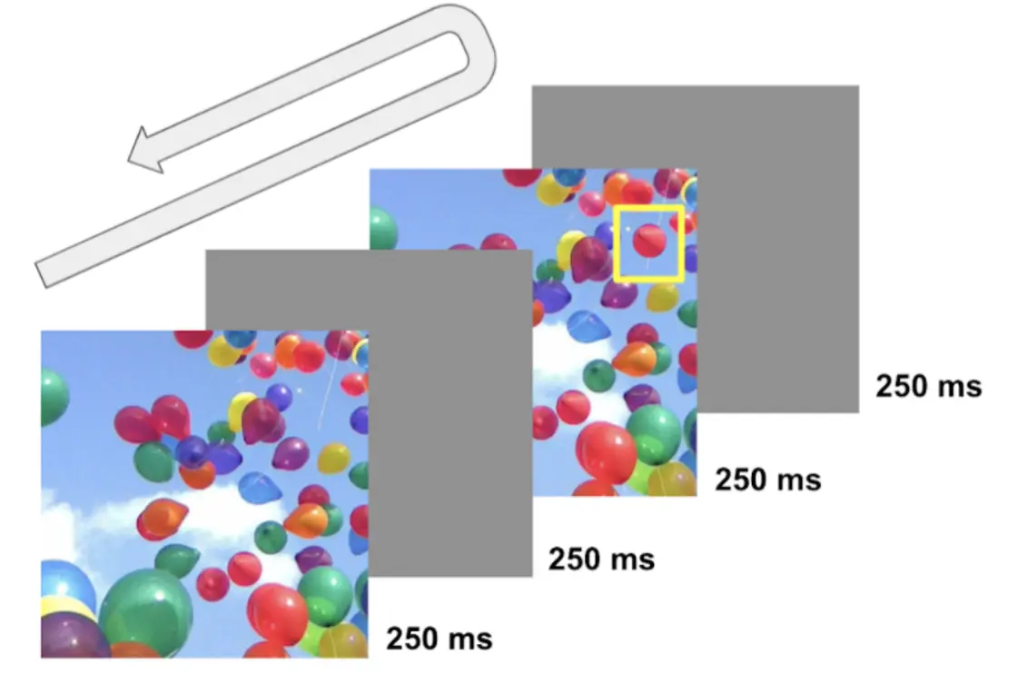 Figure 2. Display of sample trial. In this looping sequence, the four frames are serially displayed until the mouse response is made. The changing target (red balloon) is shown in the yellow box. With the response input, the observer is presented with a fixation cross with a message prompting them to move the mouse cursor to the center display.
Part I: Variable Determination with Lavanced Factor Tree
Consistent with the other study walkthroughs, determining the variables and their levels (or categories) would be the essential first step to plan the conditions and subsequent trial setup. First, refer to the Factor Tree located on the left side of the Labvanced display to determine the factors (or independent variables) and their associated levels. For the current walkthrough, the factors and their levels will be as follows:
Trial Group → Main trials
- Factor 1 - Change
- a. Level 1 - Addition (target appearing in the edited image)
- b. Level 2 - Removal (target disappearing in the edited image)
- Factor 2 - Quadrants
- a. Level 1 - Quadrant 1 (change is happening at the quadrant 1 area)
- b. Level 2 - Quadrant 2
- c. Level 3 - Quadrant 3
- d. Level 4 - Quadrant 4
The full display of this setup in the Factor Tree is also depicted below (see Figure 3A). With this 2 X 4 orthogonal setup, Labvanced will create eight different conditions (see Figure 3B) in the Trials & Conditions with each factor combination. As depicted, this leads to all possible combinations of Change Type X Quadrants. Also, we can determine the number of trials per condition, and we will determine eight trials per condition - a total of 64 trials.
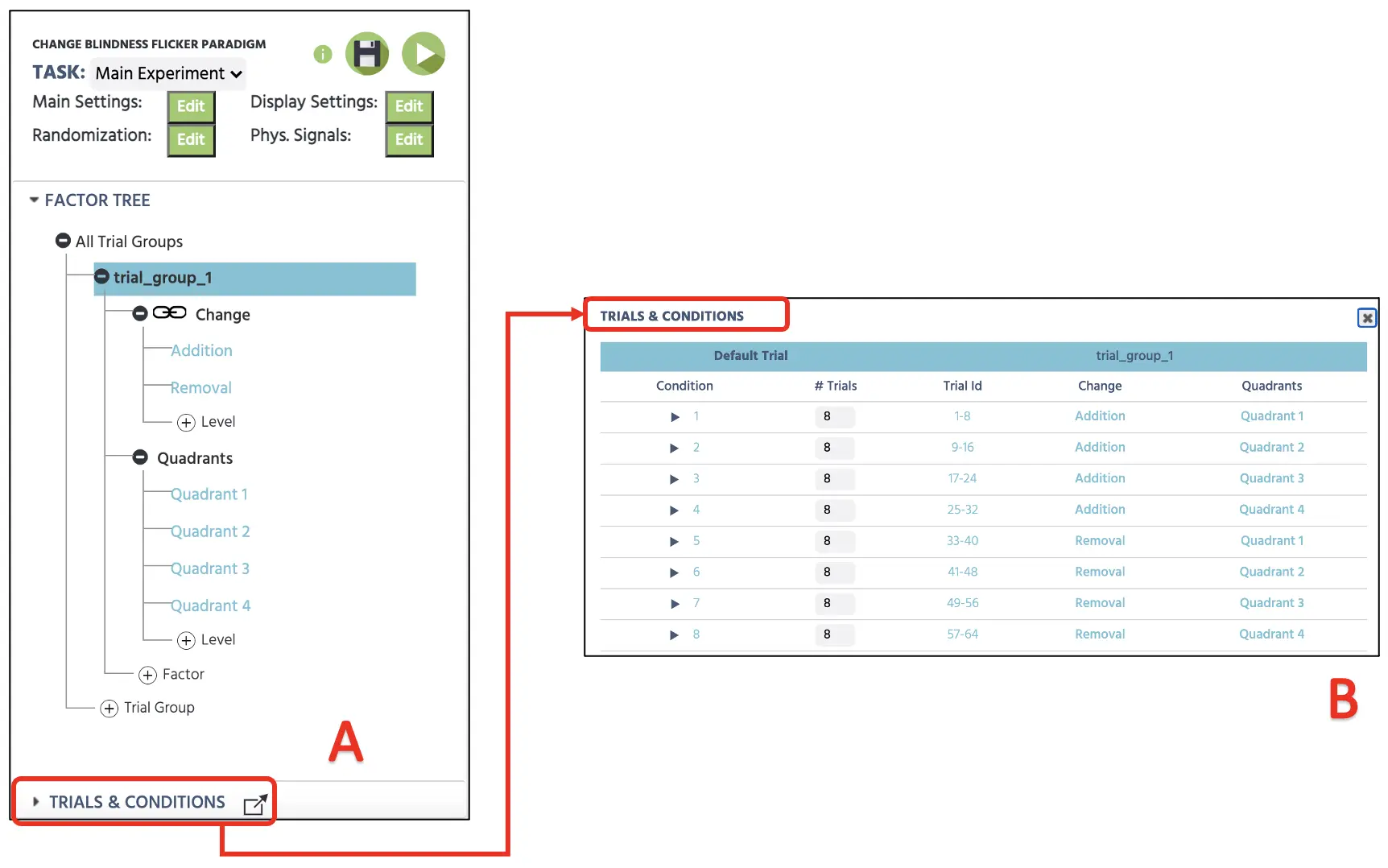 Figure 3. Canvas setup depicting catch trial setup (A) and the four trials setup within the Trials & Conditions (B).
For these 64 trials, the Labvanced will automatically vary the trial presentation depending on the Randomization Setting (see Figure 4). The default setting will remain the first Random option that will generate a random trial sequence, but this could be pre-determined with different possibilities (Fixed by Design or Hand). The current study will proceed with Random without any constraints, and this will randomly vary the trial presentation. For more information about the Randomization setting, please use this link for more details.
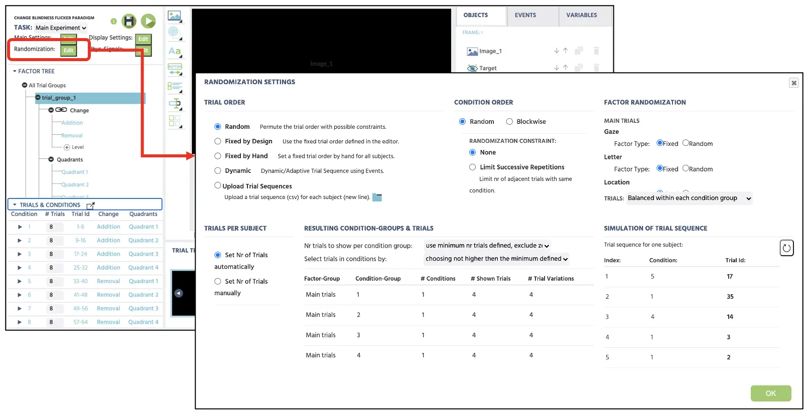 Figure 4. Display of Randomization setting with selected Random option to randomly present the trials without any constraints.
Part II: Frames setup
The second part of this walkthrough will create frames (stimuli presentation) that the participants will see during their participation. Again, the current change blindness flicker task will follow the general procedure mentioned above (see Figure 2). As depicted, a trial will begin with the first image (frame 1) for 250 ms, followed by the presentation of the first gray flicker (frame 2) for 250 ms. This will then proceed to the second image (frame 3) for 250 ms and display the final gray flicker (frame 4) for 250 ms. The four frames will continually loop (frame 1 → 2 → 3 → 4 → back to 1) until the observer clicks the changing target using the left mouse response. Following the mouse response to the changing target, a fifth frame will be present that instructs the participant to move the mouse cursor to the central display cross to control its position every new trial.
The construction of these frames will begin by clicking on the Canvas button at the bottom of the Labvanced display (see Figure 5A). Clicking this five times will display five new frames, and we will immediately name each frame (e.g., Image 1, Flicker 1, Image 2, Flicker 2, Message) to maintain the study organization (see Figure 5B). Before proceeding, it would be essential to click on the Default trial to make sure this row is highlighted (see Figure 5C). This part serves as the default template for all the conditions below. While highlighted, any changes in the four frames will apply to all conditions (i.e., adding a fixation cross in the 1st frame will apply to all 64 trials), so this would be convenient to avoid unnecessary and repetitive setups. Lastly, we will have the background color be black for all five frames, which we could set up using the Color option in the Frame Setting (Figure 5D).
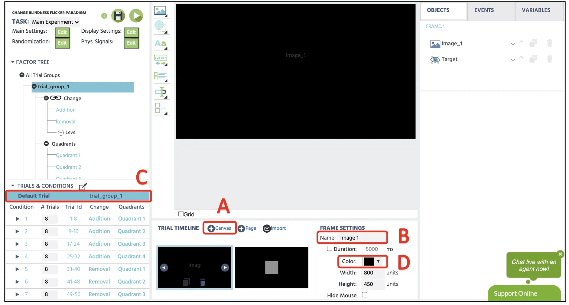 Figure 5. Display of sample trial with Canvas frame creation (A), frame name change option (B), highlight Default Trial (C), and frame color option (D).
Part III: Stimuli setup (flickers, images, and mouse instruction screen)
Frame I
With the four frames we have prepared in the last part, we will set the individual stimulus in each frame, starting with the 1st image in the 1st frame. All the 64 image pairs (unedited and edited) for this study have been prepared beforehand. The 2nd image was edited with Adobe Photoshop to add or remove an item as the changing target.
Critically, the images were edited such that eight different naturalistic images contained changes following the Trials & Conditions setup. In the 1st condition, the changing target was added to the edited image (hence the name “Addition”) appearing at the 1st quadrant. In the 5th condition, the changing target was removed (hence the name “Removal”) from the original unedited image at the 1st quadrant area. Of course, such manipulation could be different for different change blindness paradigm and theoretical investigation. Still, we will base the current setup using the conventional control for accounting for all the different types of changes in other image locations. Full access to the stimuli, including the gray flicker image, would be available following the link below.
After preparing all the picture stimuli, we would need to add them to the Labvanced file storage. To access this storage, we will click on the Media option (see Figure 6A below) and select Image to prompt the image window in the canvas. Locating the Object Properties on the right side, we can adjust the position, size, and importance and select images from the Labvanced file storage. We will import all the images by clicking on the File icon (see Figure 6B). This will open the file storage window to upload and select the stimuli we will display for each trial. As a reminder, the 1st frame will present the unedited image, and we will follow the following option for the image size and position depicted in Figure 6C.
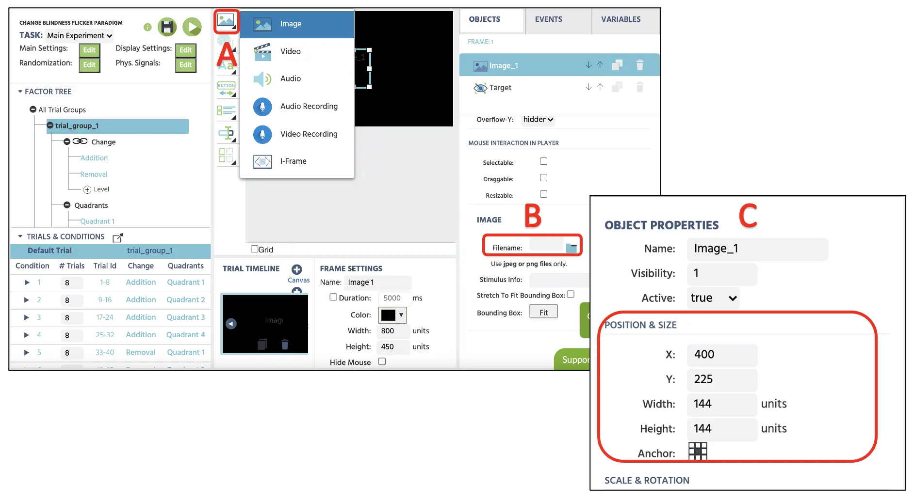 Figure 6. Display of media icon selection with highlighted image option (A). Clicking the file icon located on the right side (B) prompts the file storage to upload and select an image to display for each trial. Object properties also on the right side allow to position and edit the size for image presentation.
Frame II
In this frame, we will follow the same procedure in the 1st frame starting with Media → Image selection. The Position & Size options will mirror the previous image, and we will select the gray flicker image to present in this frame.
Frame III
The 3rd frame will also follow the same procedure in the 1st frame starting with Media → Image selection. The Position & Size options will mirror the previous image. Importantly, we will select the edited image associated with the 1st frame that contains the changing target.
Frame IV
In this last frame, the procedure will precisely mirror the 2nd frame starting with Media → Image selection. The Position & Size options will mirror the previous image, and we will select the same gray flicker image that we used in the 2nd frame.
Finally, it would be crucial to set one last object, known as the Invisible Element, in all the frames. This is accessed by Shapes → Invisible Element (see Figure 7), and we will need to precisely position this element on top of the changing target location for all four frames.
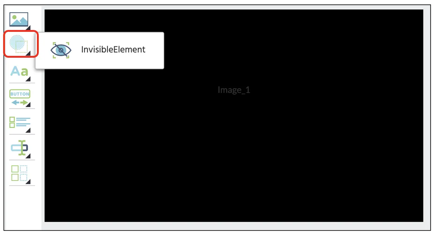 Figure 7. Display of shape icon in the red box to select the Invisible Element.
The importance of this setup is that we are specifying the Labvanced program where the changing target is specifically located throughout this invisible element that we can direct the program but not visible to the participant. Otherwise, the program can’t differentiate the background and the changing target. Furthermore, this would be essential to link with the mouse click response later in this walkthrough. The invisible element will be set with the same size and location across all four frames (see Figure 8). The position will vary depending on the quadrant condition and changing target size.
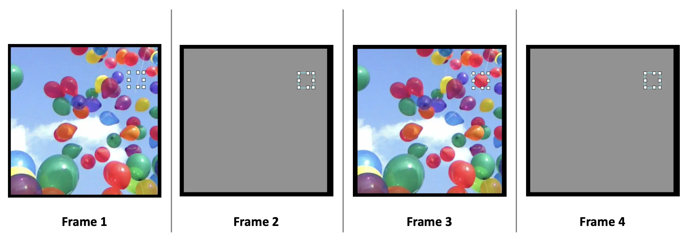 Figure 8. Display of 4 frames with invisible elements indicated in a rectangle box. In this example, the changing target is the red balloon added to the 1st quadrant location. The size and location of the invisible element indicating the target are the same in all four frames.
Frame V
In this final frame, we will create a fixation cross in the center frame, prompting the observer to move the mouse cursor to the fixation. This is an essential control for the current task involving the visual search, as the mouse position could bias the target detection if the followingdepends on target location appears around the recently presented area. With this control, each unique trial will proceed with the central location of the mouse cursor.
To set the fixation and the instruction message, we can start by clicking on the Display Text (see Figure 9) to implement the textbox in the canvas. Here, we can type in the + in the box with a font size 36 and position it in the display center. We will then create one more Display Text and include the message as depicted below (see Figure 9).
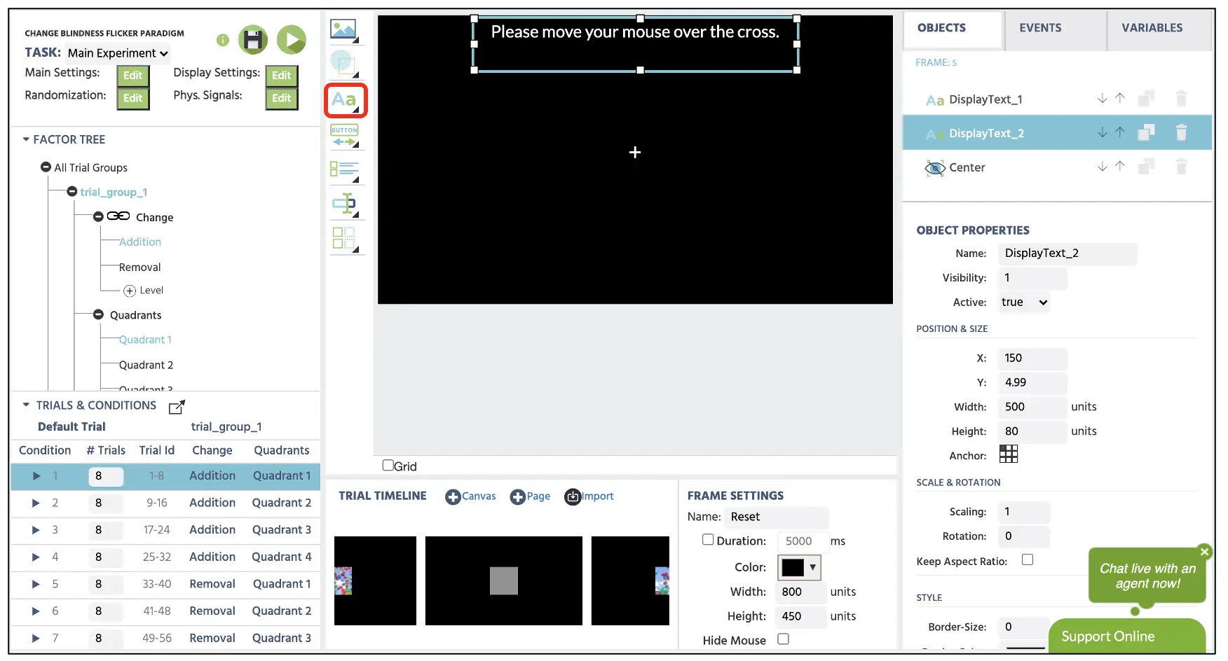 Figure 9. Display of 5th frame with the Text Display option indicated in the red box.
With that completion, we now have all the stimuli displayed in this section. We will now move onto Part 4 to program the logical sequence that the Labvance will initiate in each frame.
Part IV: Events setup (display duration, target detection, and variable recording)
Before proceeding, we will create two new variables to store the reaction time measurement for the target detection and record the number of times the sequence lopped to calculate the detection time. We need the latter because the program will give us the reaction time from the frame onset, but this reading is independent of the number of cycles it went through for all four frames. We will click on the Variables on the top-right display and select Add Variable to create these new variables. We will proceed with the following steps for the names and types indicated below in bullet points (also in Figure 10 below).
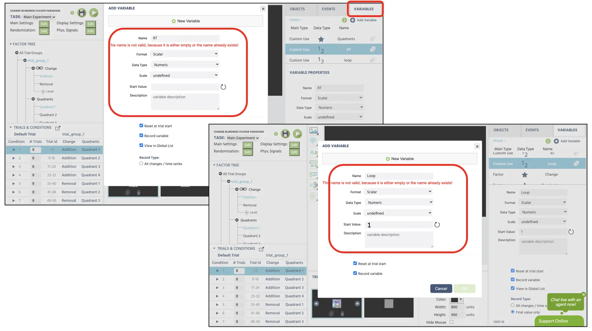 Figure 10. Display of new variables (Response Time & Loop) creation. Both variables are set with the numeric data type. Notably, the Loop variable’s starting value is specified with 1 to indicate the first loop count during the trial beginning.
Following the general frame sequence mentioned in the introduction (see Figure 2 above), we will create the Event structure separately per frame. In frame 1, we will establish separate Events for:
- A. 250ms image 1 display
- B. Loop counting system
- C. Mouse response recording
- D. Frame name recording.
Frame 1A Event: Image 1 display
For the first Event, we want to present the first (unedited) image 1 at the center of the display for 250 ms. Therefore, the logical sequence in this first Event is:
- As soon as the frame starts
- Wait 250 ms
- And then jump to the next frame
To create this Event, click on the Events on the top right next to the Variables and select Frame Event (on this frame only). In the first window dialogue, we can name the Events as “Show image” (Figure 11A) and click next to proceed to the Trigger option. The trigger type is Trial and Frame Trigger → Frame Start (following the 1st logical sequence above; see Figure 11B). With this trigger, we want to initiate the 250 ms frame delay action (2nd logical sequence); therefore, this can be set with Add Action → Delayed Action (Time callback) and specify 250 ms in the delay box (see Figure 11C). Finally, for the last logical sequence, click on Add Action in the Action Sequence box and proceed with Jump Action → Jump to → select the Next Frame (see Figure 11D).
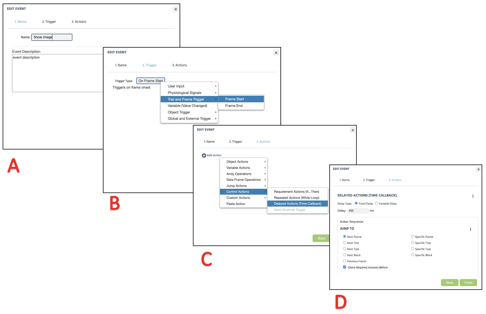 Figure 11. Display of first Event creation for fixation cross (frame 1) presentation following Event naming (A), Trigger (B), Action determination (C), and Action execution (D).
Frame 1B Event: Loop count
For this 2nd Event, we are specifying the program to count the number of times the 1st frame was shown to serve as the loop count. Therefore, the logical sequence in this second Event is:
- As soon as the frame starts
- Add the numeric value 1 to the existing Loop variable.
To create this new Event, click on the Events on the top right next to the Variables and select Frame Event (on this frame only). In the first window dialogue, we can name the Events as “Loop count” and click next to proceed to the Trigger option. The trigger type is Trial and Frame Trigger → Frame Start (following the 1st logical sequence above). With this trigger, we will set the loop count to the Loop variable by Variable Action → Set/Record Variable (See Figure 12A). On the left side, we will assign the Loop variable and perform the arithmetic action on the right (See Figure 12B). In the arithmetic box, we will store the same Loop variable on the left and proceed with the +1 process (see Figure 12C).
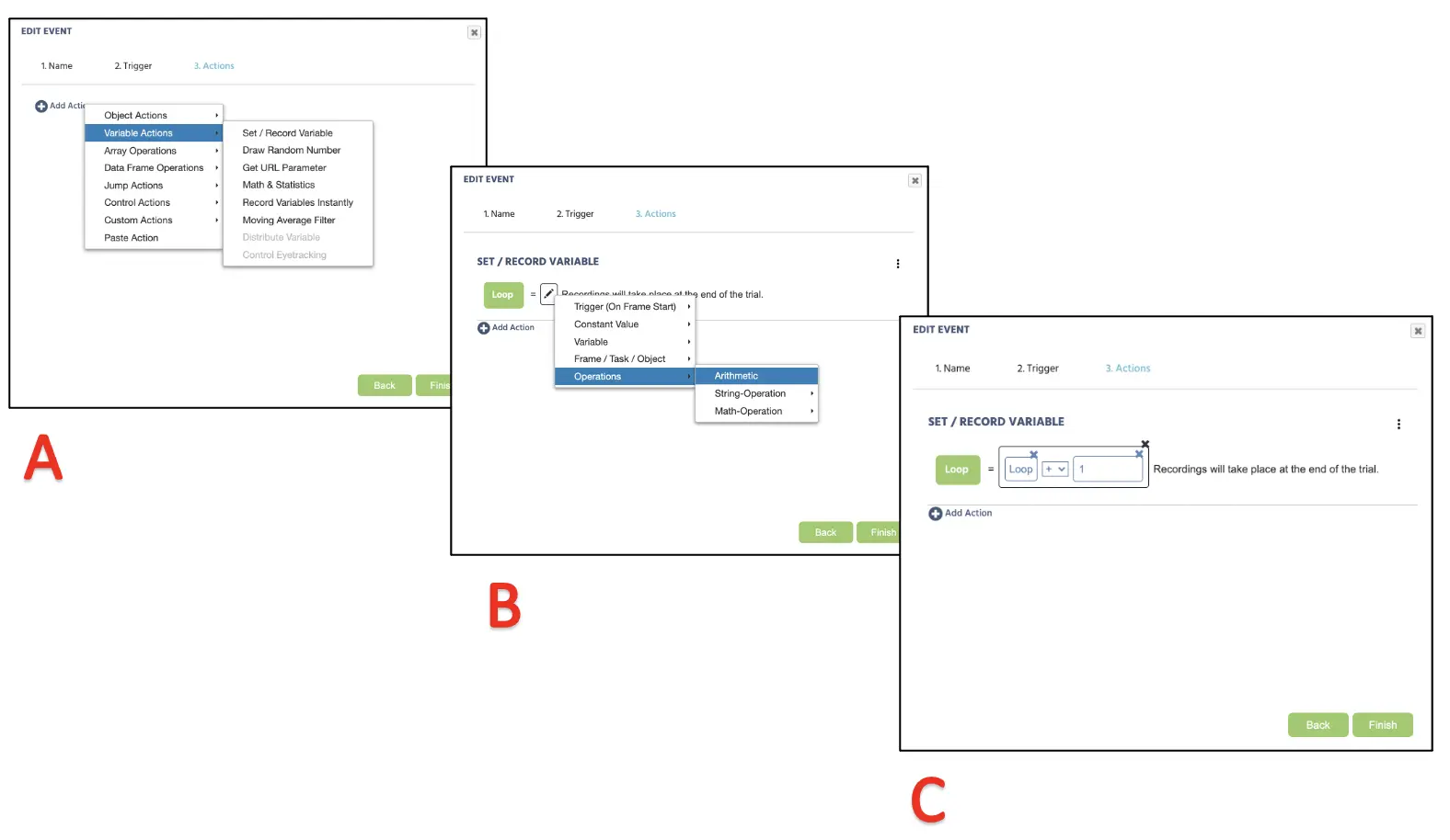 Figure 12. Display of second Event creation for the loop count following set/record (A), arithmetic selection (B), and operation (C) to increase the loop count by per every Frame 1 presentation.
Frame 1C Event: Mouse click response recording
For this 3rd Event, we are specifying the program to record the mouse click response to the invisible element that we established to indicate the changing target location. Importantly, we will record the reaction time of target detection to the RT variable we created earlier. The logical sequence in this third Event is:
- When the mouse click response is made to the target (invisible element)
- Record the reaction time from the frame onset (ms)
- Jump to the 5th message frame
To create this new Event, click on the Events on the top right next to the Variables and select Frame Event (on this frame only). In the first window dialogue, we can name the Events as “Target detection” and click next to proceed to the Trigger option. The trigger type is User Input → Mouse Trigger (following the 1st logical sequence above). In the same window, we will leave the default settings of Action: click and Button: left, but set the trigger as the invisible element that we created (see Figure 13A). With this trigger, we will set the action to record the reaction time by selecting Variable Action → Set/Record Variable (following the 2nd logical sequence). On the left side, we will set the RT variable and perform the arithmetic action on the right. On the right, proceed Frame/ Task/ Object → Frame → Time From Frame Onset (see Figure 13B). With this, not only are we asking the program to record the mouse click RT in ms. Finally, we will have the mouse response to jump to the mouse centering message screen, and this will be begin by clicking Add Action → Jump Actions and select Specific Frame → Message (following the 3rd logical sequence; see Figure 13B below). Click Finish at the bottom of the window to complete the final Events setup for this study.
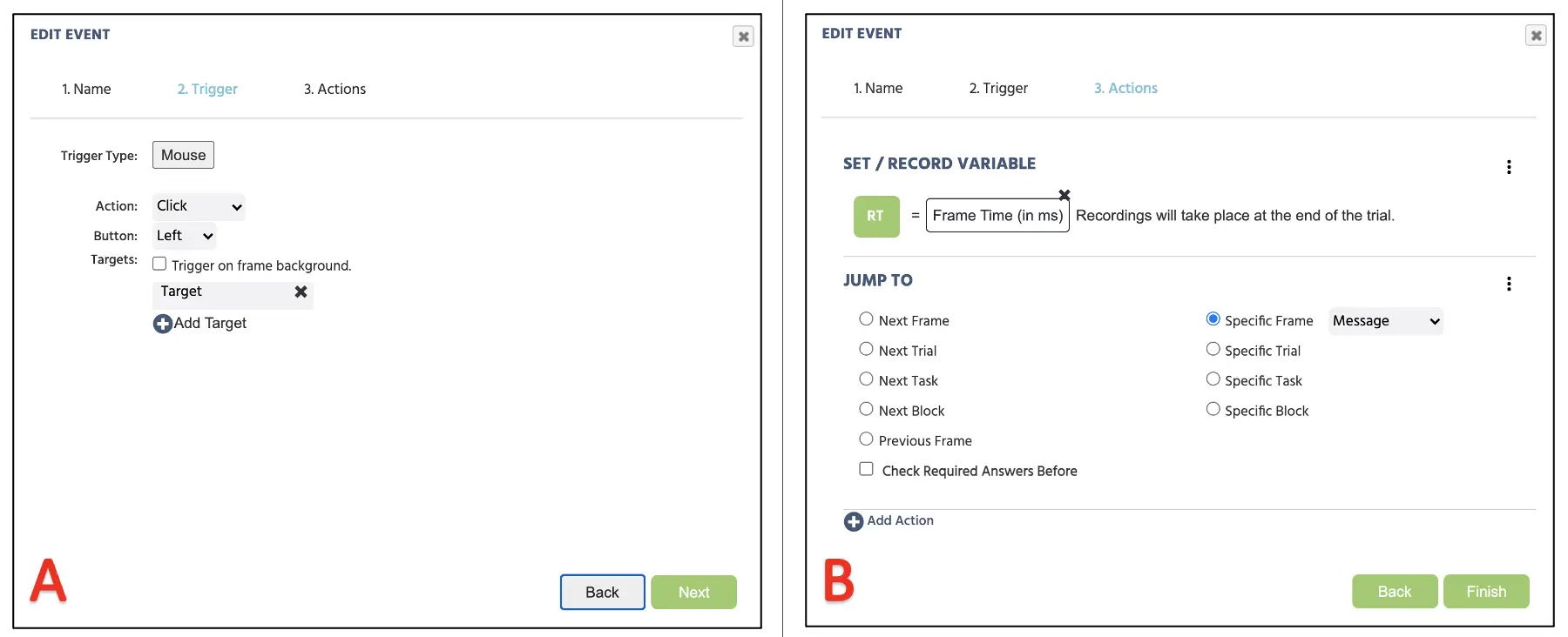 Figure 13. Display of third Event creation for the mouse trigger setup (A) and specifying reaction time recording and proceeding jump action to the message frame (B).
Frame 1D Event: Frame name recording
For this 4th Event, we are specifying the program to record the last frame in the trial when the mouse click response is made. This would be a critical information to calculate the total reaction time that it took for the participant to notice the changin target, considering the loop count and the frame onset (ms) recording that occurred in a specific frame. The logical sequence in this fourth Event is:
- As soon as the frame ends
- Record the frame name to the Frame name variable
To create this new Event, click on the Events on the top right next to the Variables and select Trial Event (on each frame). Unlike the previous Frame creation, Trial Event will apply the Event specification to all five frames in our study. In the first window dialogue, we can name the Events as “Frame name” and click next to proceed to the Trigger option. The trigger type is Trial and Frame Trigger → On Frame End (following the 1st logical sequence above; see Figure 14A). In the next Action dialogue, proceed with Variable Action → Set/Record Variable (following the 2nd logical sequence). On the left side, we will set the Frame name variable. On the right, proceed Frame/ Task/ Object → Frame → Frane Name (see Figure 14B). Click Finish at the bottom of the window to complete the final Events setup for this study.
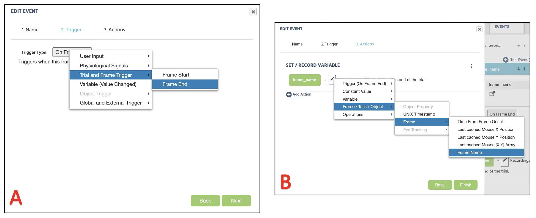 Figure 14. Display of fourth Event creation for the frame end recording starting with Frame end trigger (A) and Frame name recording action (B).
With we have successfully established all the necessary Events for the first frame! The procedure for the second (flicker 1), third (image 2), and fourth (flicker 2) frames will mirror the same procedure, except for the Loop and Frame name Events. Meaning, we will need to create Events 1A and 1C for the frames 2, 3, and 4, and the last 5th frame containing the mouse centering message will involve entirely different Event structure. With that in mind, please set the Events for those frame before proceeding to the 5th frame Event set up.
Frame 5 Event: Mouse centering instruction
For this last Event, we are displaying a message to the participant to move the mouse cursor to the central fixation to reset the mouse position. The logical sequence in this last Event is:
- As soon as the mouse cursor hovers over the central fixation
- Jump to the next rial
To create this new Event, click on the Events on the top right next to the Variables and select Frame Event (on this frame only). In the first window dialogue, we can name the Events as “Mouse centering” and click next to proceed to the Trigger option. The trigger type is User Input → Mouse Trigger (following the 1st logical sequence above). In the same window, we will set Action: Hover and Target: Center (central fixation cross; see Figure 15A). With this trigger, we will proceed to the action of Add Action → Jump Actions and select Next Trial (following the 2nd logical sequence; see Figure 15B below). Click Finish at the bottom of the window to complete the final Events setup for this study.
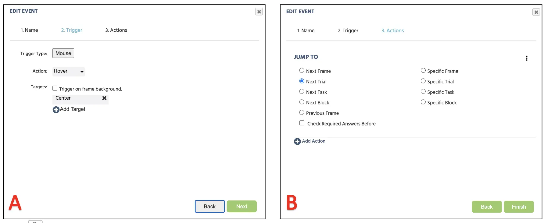 Figure 15. Display of Event creation for the mouse trigger setup (A) and jump action to the next trial (B).
Part V: Block setup
With this final setup, we now have a working Posner’s gaze cueing paradigm comprised of 36 trials in this block. Depending on the study, researchers may need to present multiple blocks of 36 trials to the participants depending on their investigation. Fortunately, Labvanced allows organizing the study in the Study Design page to organize different blocks (see Figure 16).
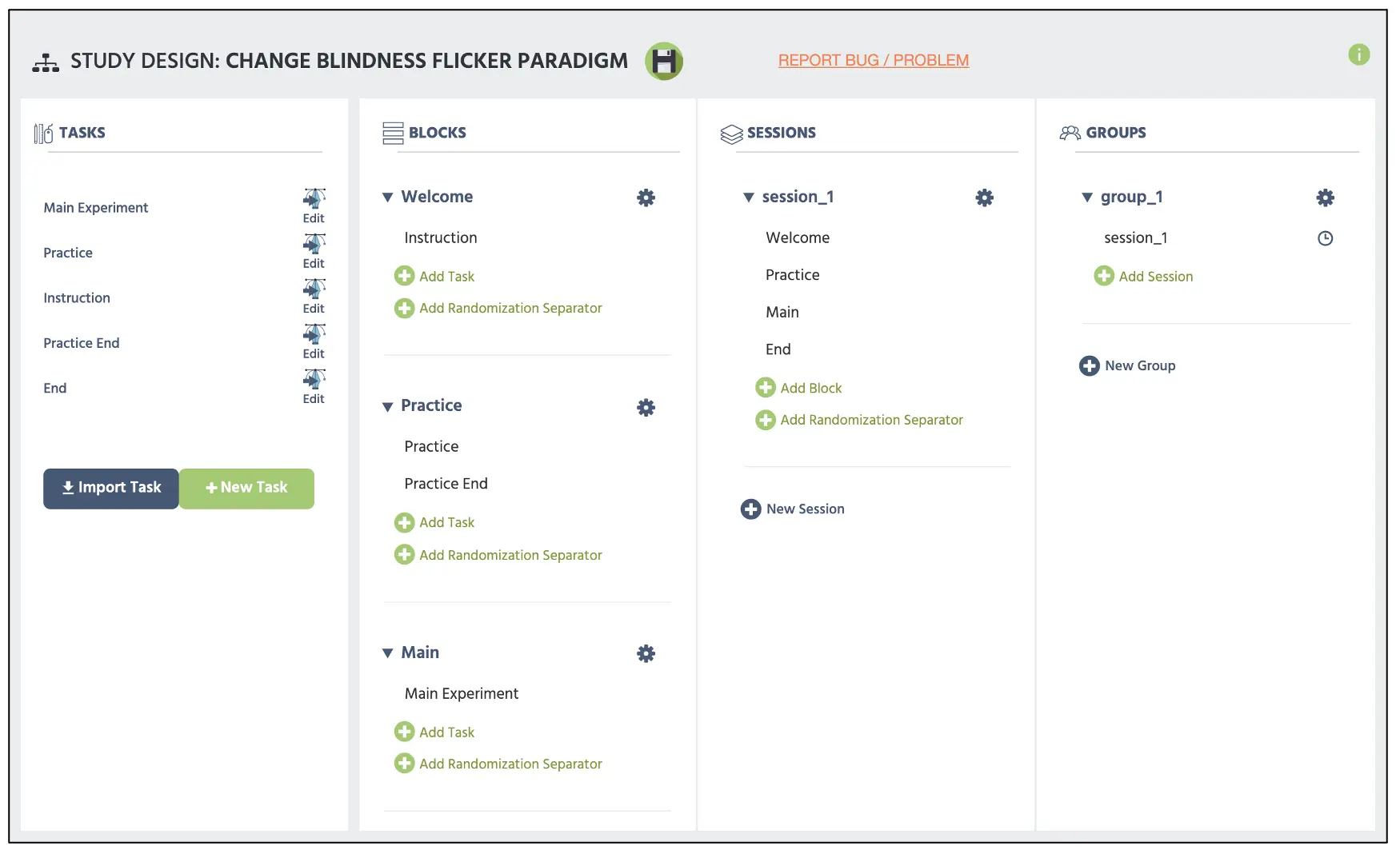 Figure 16. Display of main Study Design page with the top red box displaying two parallel bars serving as the Randomization separator added by the Add Randomization Separator below.
The only thing that remains in this walkthrough is the instruction/consent document, practice block, demographic questions, and other protocols, but that varies based on the researcher and institution to halt this walkthrough. For more information on text creation, please view our resources link for additional information. Furthermore, the constructed study is also available as the template in our Library using this link along with other experimental paradigms. With that said, on behalf of the Labvanced team, I hope for the best in all your scientific endeavors and pray that this walkthrough serves as an important cornerstone for your study construction.